

-

2019-11-25
-

103
The demand for renewable energy is on the rise. Renewable energy, depends on sources other than fossil fuels to generate power, does not drain our world of critical resources, and does not adversely affect the environment. The primary focus of commercially available new energy technology right now is solar photovoltaic(PV) power generation, which harnesses the energy of the sun and converts it into usable electricity.
Figure 1 is a typical solar PV power generation system. In this system, solar PV arrays generate electricity from sunlight, which is converted from DC to AC using an inverter, then AC electricity is fed into the grid for home or business, or is used to charge the batteries by the power conversion system (also known as energy storage bi-directional inverter). The power conversion system supplies power based on the supply-demand balance of electricity.
In a centralized or distributed electricity generation system network, a centralized or distributed inverter is the heart of solar PV system. The safe and reliable turn on or turn off for the IGBT full-bridge is the most critical part of the overall system design and the most reliable part during inversion in DC high voltage and high power systems. Therefore, it is necessary to ensure the operation logic of the control unit reliably , and to maximize the insulation characteristics between each monitoring control units or dangerous electrical circuits in circuit design of IGBT drive control units.
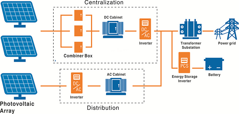
Figure 1: Solar PV Power Generation System
Figure 2 is an example of inverter systems. Generally, there is a DC/DC converter (PV60-27D1215) in the front end to take electricity from DC bus and convert it into 24Vdc to supply power to the control unit. The isolation voltage of this DC/DC converter should be 4000Vac or higher to ensure the safety and reliability between high voltage bus and control unit circuit. The system drive isolation unit is connected between IGBT and the system control board, so that the drive unit is required to have high insulation characteristics to ensure stable and reliable operation of the main control system.
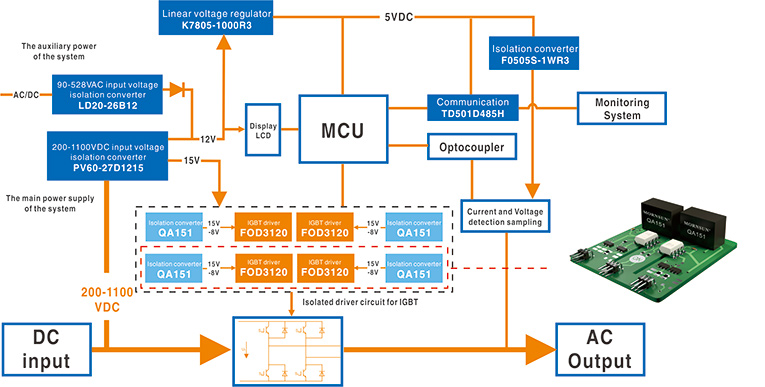
Figure 2: Block Diagram of A Distributed Inverter
What are the specific requirements for a safe and reliable IGBT drive board?
The IGBT drive circuit is mainly used to isolate, transmit, amplify the control pulse signal to drive the power to achieve reliable, stable, safe driving of the IGBT power device. Following requirements are suggested to be considered during IGBT drive board design:
a) In the inverter unit, the IGBT full-bridge circuit is widely used, which can effectively avoid the possibility of simultaneous conduction between the upper bridge and the lower bridge IGBT, and the short-circuit fault occurred in the inverter system at high and low voltages. Therefore, a safe, reliable, strong anti-interference, accurate logic drive control chip is a must.
b) According to operating characteristics of IGBT, the junction capacitor Cge needs to be charged or discharged when the IGBT is turned on or off. Therefore, the gate drive DC/DC power supply is required to have asymmetrical positive and negative dual output voltages and meet the requirements of transient charge and discharge current of junction capacitance to ensure that the IGBT can be turned on and off quickly.
C) When the DC high voltage inverted to AC voltage, the IGBT generates high frequency and high amplitude interference signals during fast turn-on and turn-off. Therefore, the drive circuit should feature high anti-interference ability, high isolation voltage and low isolation capacitance, to ensure reliable operation of the drive circuit and to avoid common mode interference signal conduction to the system control board.
d, The operating environment of the IGBT is large current and high voltage, which causes a high temperature rise inside the system during inversion, so that the gate drive DC/DC power supply is required to have a high operating temperature range.
How does the ON Semi driver demo board work?
Figure 3 illustrates how the On Semi driver demo board works. In this circuit diagram, terminal 2 and terminal 14 are connected to the gate level (G), terminal 2 of FOD3120 chip is connected to the control signal. When the control signal is high, the chip outputs a high level, the NPN transistor (2SC5569) is turned on, the PNP transistor (2SA2016) is turned off, the positive output terminal (+V0) of the power module QA151 is connected to the gate level(G), and the IGBT is turned on. When the control signal is low, the chip outputs a low level, the NPN transistor (2SC5569) is turned off, the PNP transistor (2SA2016) is turned on, and the negative output terminal (-V0) of the power module QA151 is connected to the gate level(G), and the IGBT is turned off.
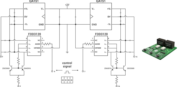
Figure 3: Circuit Diagram of ON Semi Driver Demo Board
 MORNSUN QA151 is a DC/DC converter specialized for IGBT driver. It adopts the mode of mutual connection after two independent outputs which makes it an ideal choice for ON Semi to power its driver IC ON FOD3120SD and transistors 2SC5569, 2SA2016.
This QA151 power module integrates driving IC’s features and provides +15/-8.0VDC asymmetrical output voltages which reduce the driving consumption to the minimum extent and meet the requirement of fast turn on or turn off.
QA151 also offers a wide operating temperature range from -40℃ to +105℃ and comes in a compact, internally-potted 7-pin SIP case measuring 19.5 x 9.8 x 12.5 mm, which not only meets the requirements of distributed design or SIP board card design, but also simplify the system’s space layout.
Thanks to using isolated transformer, the isolation voltage of QA151 is up to 3000Vac that makes On Semi’s driver demo board has a high level of isolation. In addition, QA151’s isolation capacitance is only 6pF, which makes On Semi’s driver demo board has a strong anti-noise interference ability. With output current up to 120mA and over 200uF capacitive load, it meets a wider power requirement of IGBT.
For more information, please visit www.mornsunpower.de.


